Fan Regulator Teardown

Fan Regulator Teardown

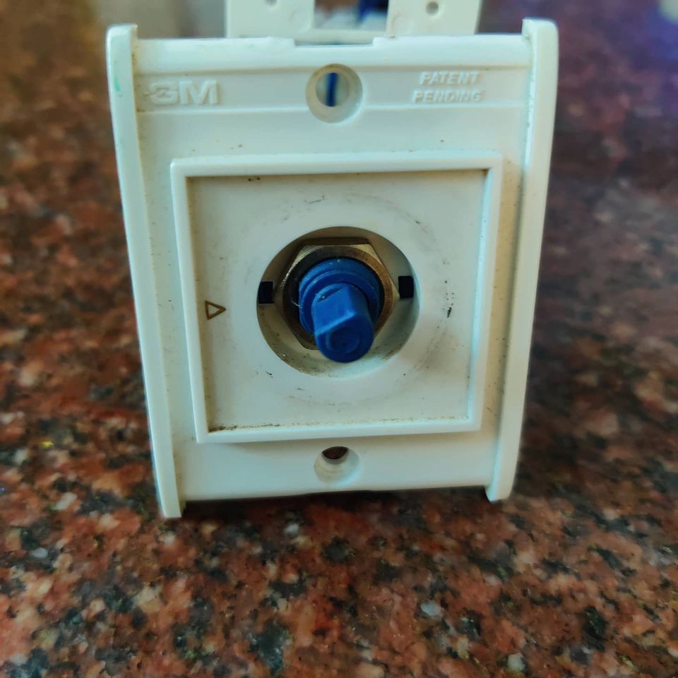
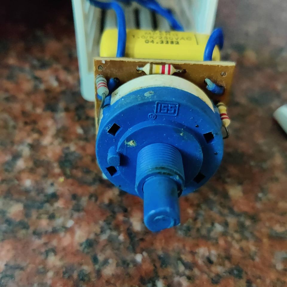
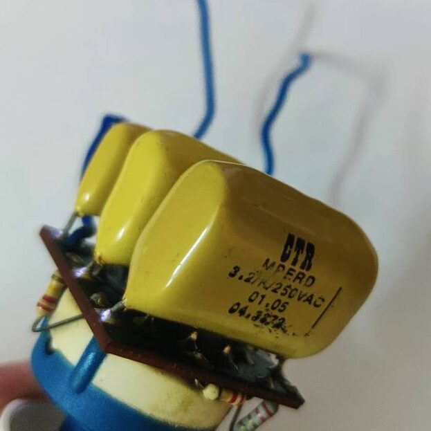
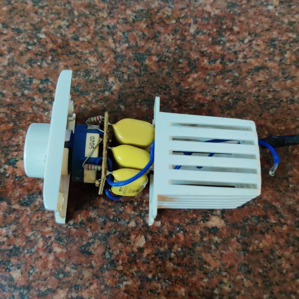
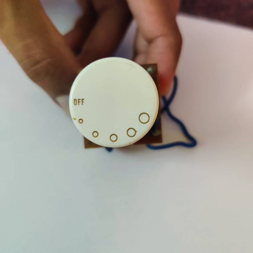
Fan regulators are connected in series with the fan. All it provides is an impedance to the fan motor. There are multiple variations of these, the one shown is a rotary discrete level type. In these, there are usually 6 rotatable positions for the knob(incl. OFF). At each position, there is a metalised film capacitor which provides impedance in series. For lower positions, lower capacitance kicks in, meaning higher impedance (Capacitance and Impedance have inverse relation) to AC. There are 3 capacitors (1uF, 2.2uF, 3.2uF usually) for 3 positions, for the fourth position they put 2 of these in parallel to get a higher capacitance and an even lower impedance. At position 5, its direct connection to the motor for no impedance and full motor speed.

Usually, the fault in these devices is that the higher capacitors blow up(Fan won’t work on higher speeds) Or get shorted, so your fan will run at lower speeds but when you switch to level 3 or higher, the fan always runs in high speed irrespective of the position. You just need to buy a rated capacitor(INR 10, $0.1) and solder it to the board to fix the problem.

It’s not that these regulators are expensive to replace, like in my case, I can’t find the same model of regulators in the shop anymore and it will ruin the aesthetics of the rest of the switches on the board, to have a weird design regulator sitting there.

Fan Regulator Teardown
If you liked the post, Share it with your friends!

Capacitive Dropper

Probably one of the most common and cheap power supply circuits used to power low current applications directly from AC. You would have used these for sure at your homes in LED night lamps, fan regulators(Maybe a future post when I get time) or any of the cheap gadgets that plugin directly to your mains AC supply. The elegant part of the circuit is that it removes the need for a bulky transformer and can be built with very few components.

LED Bulb Teardown
LED Bulb Teardown
Circuit Schematic
LED Schematic with a capacitive dropper

The pictures are of LED night lamp which plugs into mains directly. It consists of a higher wattage in-rush current limiting resistor(R1, during turn ON of the device, so as to not let a large current through initially), and a capacitor(C1) in series with the mains(Instead of another resistor). The capacitor is designed to give impedance without losing power as heat at 50Hz. The resistor (R2) is a large wattage resistor which acts as a bleeder resistance to discharge the capacitor when the device is OFF(To avoid shocks if you touch it). The overall circuit has a poor Power factor but has low active power consumption. This is basically all because of the capacitive dropper circuit section.

The rest of the circuit is a four-diode bridge rectifier to convert to DC, and an electrolytic capacitor(C2) to smooth the DC at the output. This is really not needed if you really wanted to skimp on parts. LEDs will work fine on AC(you may see flickering though sometimes).

If you liked the post, Share it with your friends!
1 15 16 17 18 19 20