I came across these Dehumidifiers only recently and they seem to be the real deal. I was always on the lookout for using tech to remove water from inside smaller products, and most of the time I was stuck with peltier style ones or the silica gel units. The solid state membrane ones (called Rosahl) are from Mitsubishi Electric and seems to have around for a while.
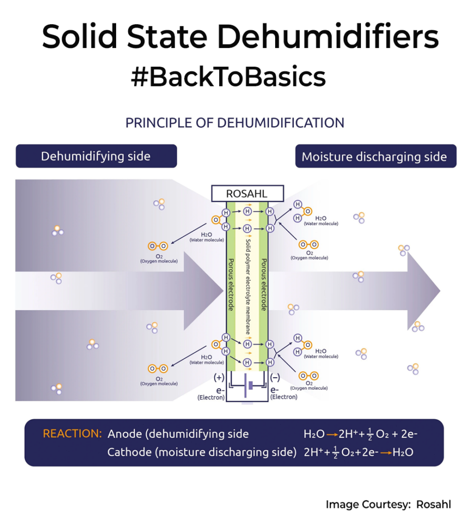
Rosahl operates using a solid polymer electrolyte (SPE) membrane. When a small 3V DC voltage is applied, it electrolyses moisture in the air. This process breaks down water molecules into hydrogen ions and oxygen(Check Images). The hydrogen ions migrate through the membrane and recombine with oxygen on the other side, releasing water vapour outside the enclosure. I find this method efficient because it doesn’t involve liquid water, making the system maintenance-free and eliminating the need for water drainage, which is a big deal for consumer products.
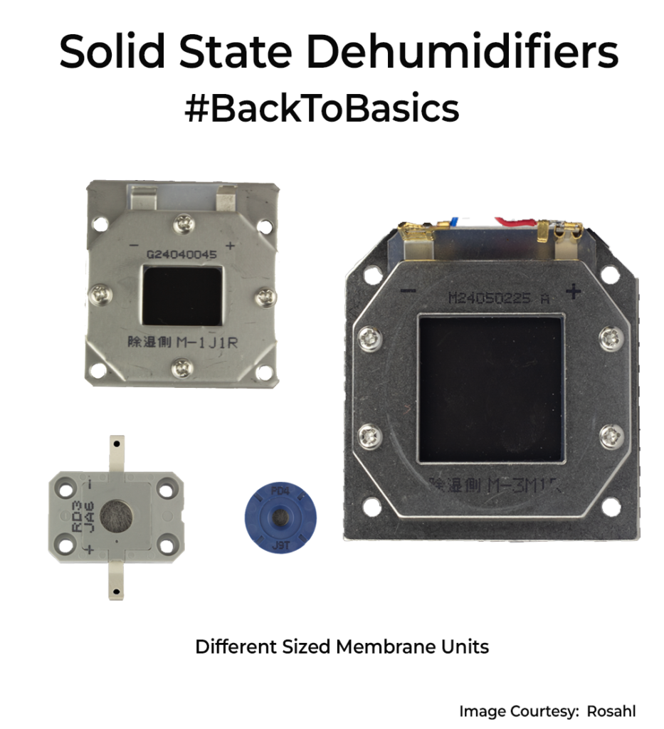
It’s designed for enclosures ranging from as small as 250 millilitres to up to 8 cubic meters and comes in various sizes. The absence of moving parts like the fan means it’s silent and vibration-free and can be used in any small product for water removal. The device uses relatively low power(60mW – 5W), and the power consumption decreases further as the relative humidity within the enclosure drops.
However, one significant drawback I’ve noticed is cost. Even the smallest modules start around $25, with larger ones exceeding $500. Also, it isn’t practical for larger spaces, like entire rooms or bigger areas. I assume scaling the membrane might reduce its efficiency and significantly drive up manufacturing costs.
I’d have loved to incorporate this tech into some of my client products if it were more affordable. Interesting tech nevertheless.