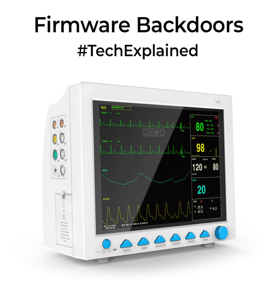
Back to Basics: OptoCouplers

Optocoupler is used to isolate two circuits and maintain the communication or control between them.

Optocouplers are one of the key building blocks of designing an isolation system. They provide electrical isolation between 2 circuits, of which one of them(Not necessarily always) is a high-voltage section. One of the main advantages of optoisolators is their ability to provide galvanic isolation, which means that there is no direct electrical connection between the input and output sides. This can prevent the transfer of electrical noise, voltage spikes, and other disturbances from one circuit to another, helping to improve the overall performance and reliability of the system.

OptoCoupler

The first versions of the optocouplers were mentioned in the patent in 1963. It consists of an input side LED and a phototransistor on the output side(Check images). When a current passes on the LED side, it glows and that light is used by the base of the phototransistor to detect that there was a change and current flows on the output side. Here the communication is effectively done via Light hence you get electrical isolation from 2 sides. The amount of isolation you get depends on the construction of the ICs and internal spacings. Usually, parts with isolation above 5KV between input and output sides are termed optoisolators. If used for isolation, always think of these as 2 separate circuits and don’t connect their grounds together. It’s a common rookie mistake to avoid.

OptoCoupler Types

Two major considerations while designing circuits with optocouplers are CTRs and Speed. The current Transfer Ratio is the ratio of the output side current to the input side current. Optocouplers are built to last for a long time, the major failure point is the degradation of LEDs(the light it emits) with time. The current through the LEDs needs to be increased to produce the same result. For digital communication circuits, you have to select units with a higher rate of transfer as it depends heavily on switching times. Always check the datasheets for speed before finalizing the part for your use case. Usually photodiodes are used instead of phototransistors for high-speed.

There are a few more design considerations which I can cover in future posts if there is interest.

If you liked the post, Share it with your friends!

Tech Simplified: SIM vs eSIM vs iSIM

SIM card Evolution

Folks who have been using phones for the last 10+yrs would have probably seen the evolution of SIM “Cards”. The Physical Plastic card(known as universal integrated circuit card (UICC)) SIMs had a large Credit card size, called 1FF(1st Form factor) in the very early 90s. The smaller one 2FF(Mini) would be one most are familiar with. The SIMs just continued to drop in size to 3FF(Micro) and 4FF (Nano) as phones wanted to pack more and more. The inherent technology used is more or less the same in these generations. Usually, a telecom operator hard-codes their details onto this plastic SIM and then the moment you put this Physical SIM in your phone, it activates and you can communicate with your mobile tower. It contains a small microchip that stores the info.

SIM Card Pinout

eSIMs(Embedded SIM) have been in the market since 2016 and have started to gain traction with higher-end phones starting to support them. It’s actually a software stack(embedded-UICC standard) that enables a user to virtually load their network profiles via an application. They “usually” come as a small chip soldered directly onto your phone’s motherboard. The form factor size is called MFF2(Machine to Machine form factor). Formfactor has nothing to do with it being an eSIM or not. There are a lot of articles wrongly mentioning that since it’s a soldered chip in MFF2 form, it’s an eSIM. eSIMs are possible with physical cards too. The benefits of eSIMs are that you can rewrite the memory and load any operator on top of it with a configuration file. Multiple profiles can be loaded on a single chip too for ease of swapping profiles. It’s not hardcoded anymore. It’s tiny and usually resistant to mechanical motion abuse as the previous generation cards. These MFF2 chips can be beefy microcontrollers(ARM Cortex M3 similar) with encryption cores.

iSIMs(Integrated SIM) are the extension of eSIMs wherein there is no external chip anymore. It’s all integrated into your chipset/SoC. It has all the benefits of eSIM but just doesn’t take up any more PCB area as it’s implemented inside the chip. In a few years’ time, pretty sure this will be the way ahead for the industry.

If you liked the post, Share it with your friends!
1 16 17 18 19 20 52