Back to Basics: Crystals and Damping Resistors

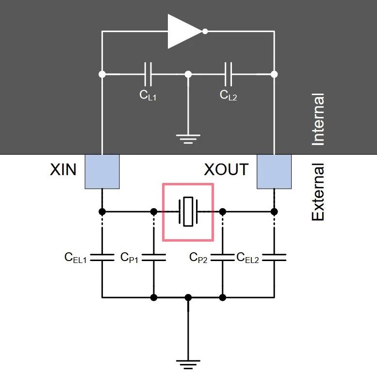
Continuing from the last post, one key element that one of my readers pointed out was the addition of an extra resistor at the output of the Pierce oscillator driver circuit in a uC. It’s a damping resistor and this is something which is not explained in a few newer datasheets and is usually ignored.
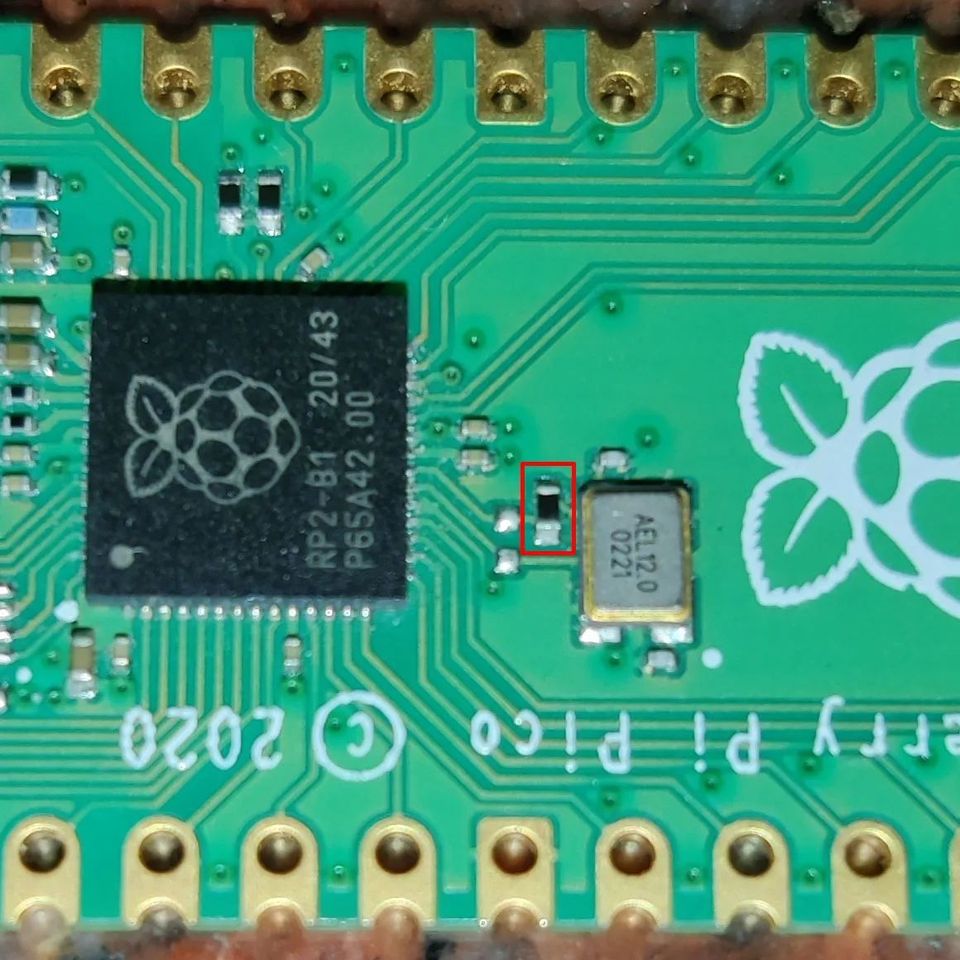
A damping resistor is needed primarily to adjust the Drive power of a crystal. Every good crystal manufacturer would add the maximum drive level in its datasheet. This is the maximum power(usually in microwatts) at which the crystal can be driven without damaging it permanently. To measure the driven level, you need to measure the current waveform to a crystal but Measuring this is a hard thing to do in the circuit. One method is to connect another know test resistance and measure the voltage difference with a differential probe to measure current. After the current is measured, test resistance is shorted out from the circuit. This is useful in SMD parts with no space. Another way is to measure it with a current probe in one of the traces. It’s expensive and hard to do on SMD parts so it’s preferred for thru-hole crystals with a probe connected around one of the legs of the crystal.
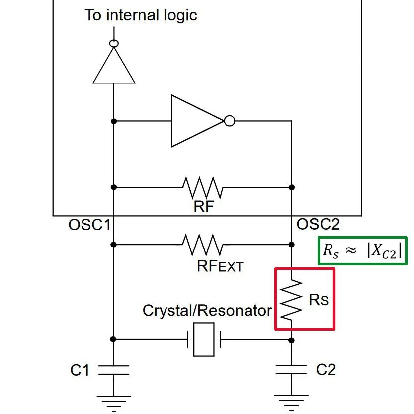
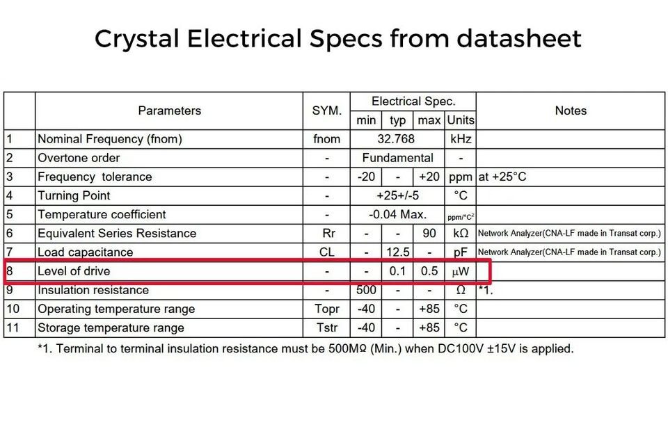
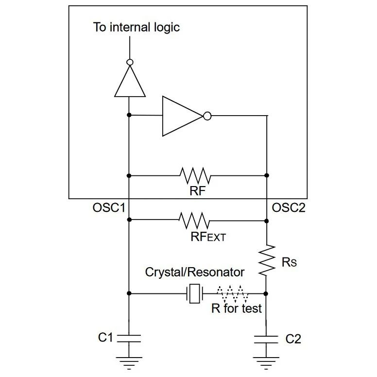
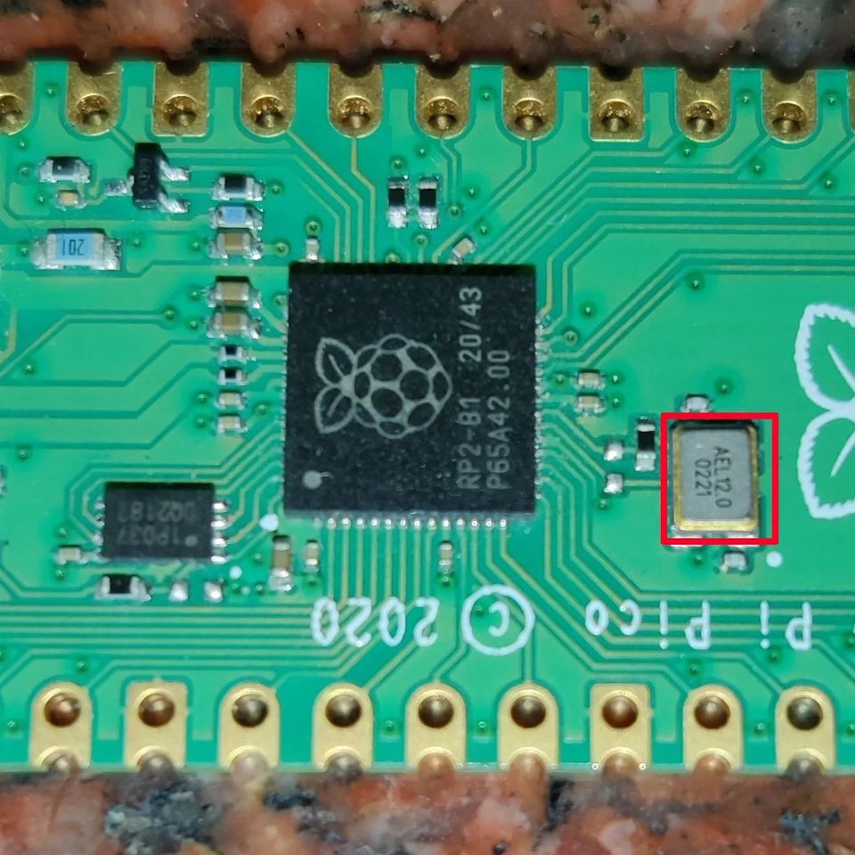
Once the RMS current to the crystal is measured, power is the squared multiplication of this current and the ESR(mentioned in the crystal’s datasheet). This power should not exceed the max value mentioned. If it does, you can try reducing the drive voltage from the uC(By adjusting the gain of the oscillator) or you add a resistor in series. The usual starting value of this damping resistor is equal to the impedance of external load capacitance(at the crystal freq) as mentioned in the figure. Using a normal voltage divider, you will see the drive will be reduced by half. Keep in mind that adding the resistor can add any additional phase shift to the oscillator circuit so you would want to double-check the crystal frequency once again in the circuit. For digital uCs these days, drive values from the Xout pin are set very low and hence you don’t see them in most datasheets.
If you liked the post, Share it with your friends!

Back to Basics: Crystals, Oscillators and Resonators

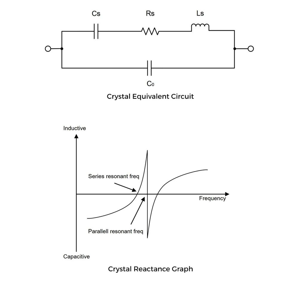
You see crystals on most circuits out there to provide accurate timing functionality to a microcontroller. Some people mistake them for devices which provide square wave “clocks” to uCs. That is not true. Quartz crystals are piezoelectric materials which can exhibit mechanical resonance. The frequency of the vibration of the crystals can be fine-tuned to a range of values out there by altering the mechanical shape and size of the crystals. Think of them like tuning forks which can be varied in size to create their desired tuning frequency. They are just passive devices which can vibrate when energy is given to them. The electrical equivalent circuit of a crystal consists of an RLC circuit with 2 resonance frequencies.

In most uCs, you have the option to connect these crystals next to the chip and these pins feed to a feedback amplifier. External Crystal + Internal Amplifier together gives you a Pierce oscillator generating an accurate waveform which is further fed to subsystems for generating your square wave clocks for timing. In most cases, you would have to add a couple of load capacitances to ground for these crystals to get the accurate freq. Do refer to the datasheets of devices to calculate these ones. Atmel has an excellent tech note on it. Startup is another consideration. It’s the time needed for an oscillator to start producing the freq at the correct amplitude after power-on. Think of it as a feedback amplifier initially taking noise as input and taking a few milliseconds to get to its steady state of actual output freq. This has high implications in low-power circuits where you want to conserve every bit of power during turn ON.

You also get oscillators as standalone chips which can be used to directly connect to your micro bypassing the internal amplifier by changing software fuse settings in the uCs. You also have something known as ceramic resonators. These are similar to quartz crystals but made of ceramic material and can also be tuned to a range of frequencies. It’s cheaper but poor Freq accuracy. Deviation of 10-50ppm for quartz & 5000ppm for ceramic.

If you liked the post, Share it with your friends!
1 31 32 33 34 35 76