I was planning to do some home networking and happened to run across SFPs. Let’s see those in detail today. SFP stands for Small Form-factor Pluggable, and it’s essentially a hot-swappable transceiver module that plugs into a switch or router port to adapt to different media types.
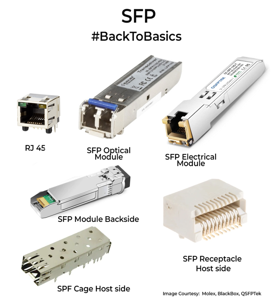
All of would know the classic RJ45 connectors, that can be used for connecting Copper cables(Cat5e) to network interfaces. As networks grew beyond 100m and speeds pushed past 1 Gbps, a better interface became necessary. Around the early 2000s, major vendors agreed on the SFP, so different manufacturers could supply compatible modules. In SFPs, you get a slot where you can choose a copper module for short runs or an optical fiber module for longer distances, even mixing multimode and single-mode fibers. That was a game-changer for cost and flexibility. SFP is a port that eases the life a bit for the designer, as they really don’t need to take care (to an extent) if it’s Copper or Optical cable on the end. No board respin needed.
Physically, the SFP “cage” connector is larger than RJ45. The SFP module fits inside the connector and has the interfacing circuitry required, freeing the host board from that footprint. It’s hot-swappable, meaning if a copper port fails, you replace just the module without powering down the device.
In practice, you will use for a copper SFP module when I need to extend a cable-run just beyond the 100 meter RJ-45 limit. For anything over a few hundred meters, or if you need immunity from electrical interference, fiber SFP (or SFP+) is the answer.
SFPs come in different types considering the speed class they cater to you. Look up on wiki for the full list. There are variations like QSFP (Quad SFP) and QSFP28, catering to 100 Gigabits of transfer speed. These are the things that move data around in data centres. In essence, SFP allows for a host of things as a pluggable interface.