Tech Simplified: SIM vs eSIM vs iSIM

SIM card Evolution

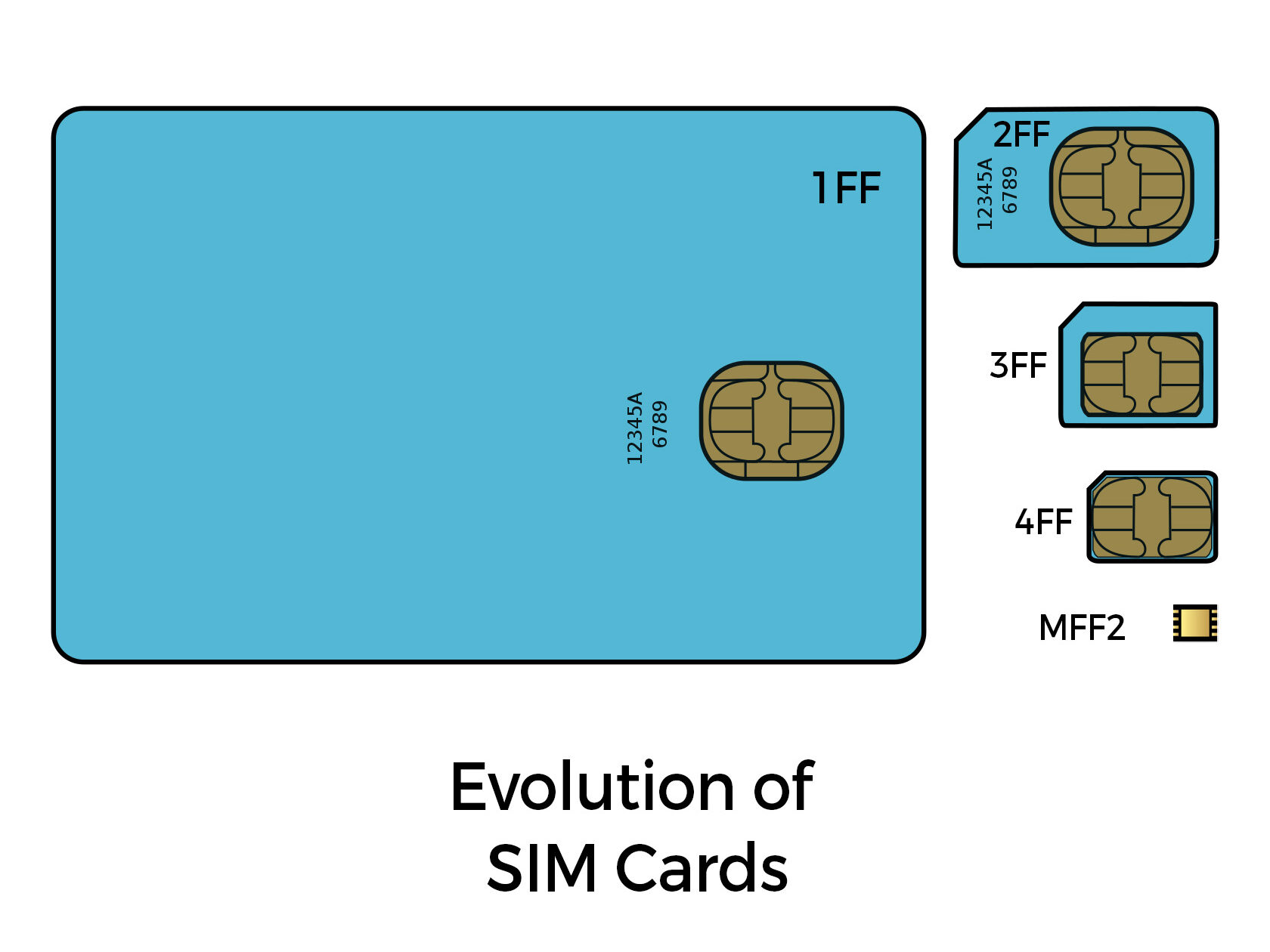
Folks who have been using phones for the last 10+yrs would have probably seen the evolution of SIM “Cards”. The Physical Plastic card(known as universal integrated circuit card (UICC)) SIMs had a large Credit card size, called 1FF(1st Form factor) in the very early 90s. The smaller one 2FF(Mini) would be one most are familiar with. The SIMs just continued to drop in size to 3FF(Micro) and 4FF (Nano) as phones wanted to pack more and more. The inherent technology used is more or less the same in these generations. Usually, a telecom operator hard-codes their details onto this plastic SIM and then the moment you put this Physical SIM in your phone, it activates and you can communicate with your mobile tower. It contains a small microchip that stores the info.
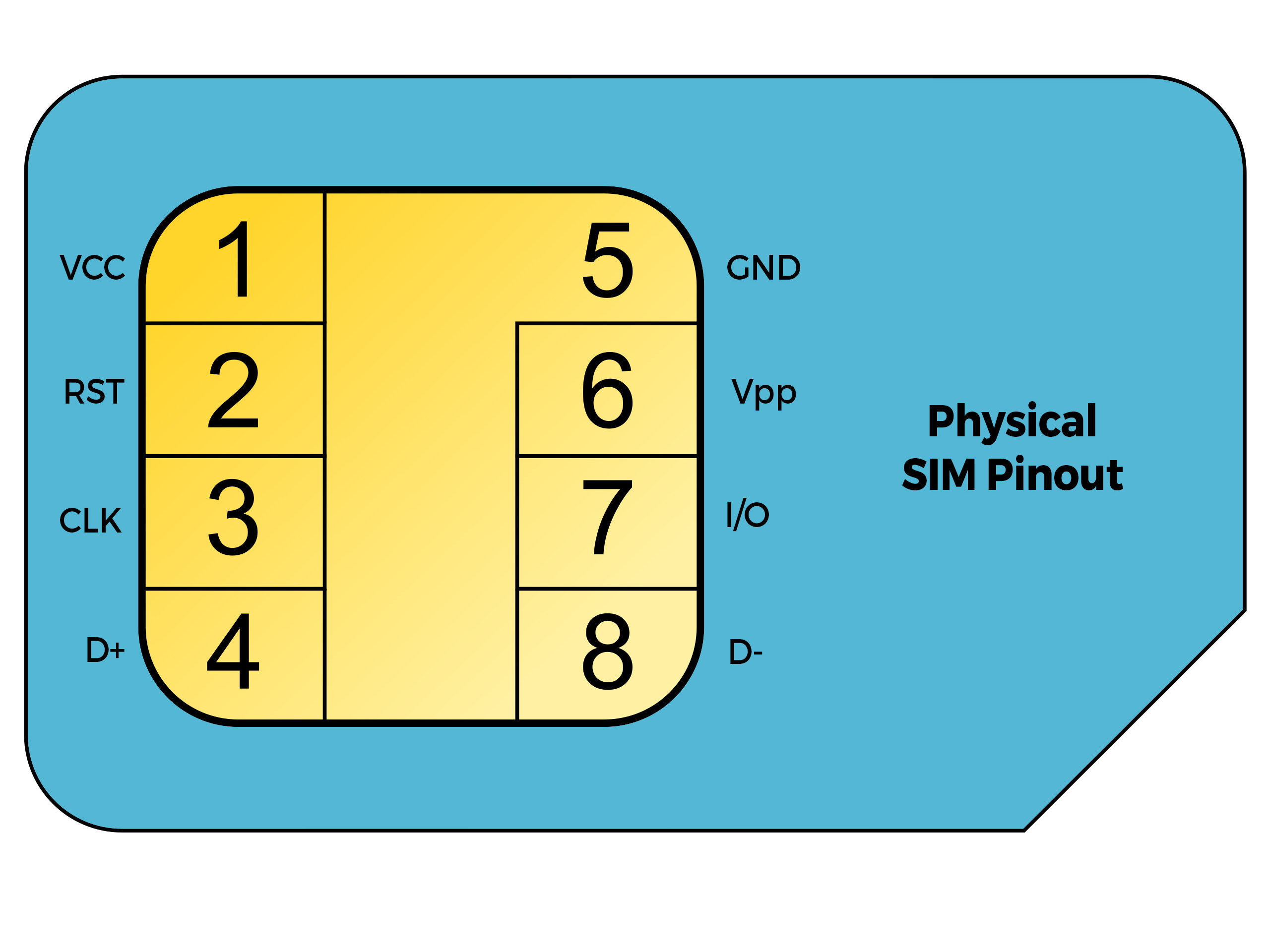
SIM Card Pinout

eSIMs(Embedded SIM) have been in the market since 2016 and have started to gain traction with higher-end phones starting to support them. It’s actually a software stack(embedded-UICC standard) that enables a user to virtually load their network profiles via an application. They “usually” come as a small chip soldered directly onto your phone’s motherboard. The form factor size is called MFF2(Machine to Machine form factor). Formfactor has nothing to do with it being an eSIM or not. There are a lot of articles wrongly mentioning that since it’s a soldered chip in MFF2 form, it’s an eSIM. eSIMs are possible with physical cards too. The benefits of eSIMs are that you can rewrite the memory and load any operator on top of it with a configuration file. Multiple profiles can be loaded on a single chip too for ease of swapping profiles. It’s not hardcoded anymore. It’s tiny and usually resistant to mechanical motion abuse as the previous generation cards. These MFF2 chips can be beefy microcontrollers(ARM Cortex M3 similar) with encryption cores.

iSIMs(Integrated SIM) are the extension of eSIMs wherein there is no external chip anymore. It’s all integrated into your chipset/SoC. It has all the benefits of eSIM but just doesn’t take up any more PCB area as it’s implemented inside the chip. In a few years’ time, pretty sure this will be the way ahead for the industry.
If you liked the post, Share it with your friends!

Back to Basics: Equivalent Series Inductance(ESL)

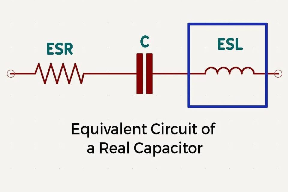
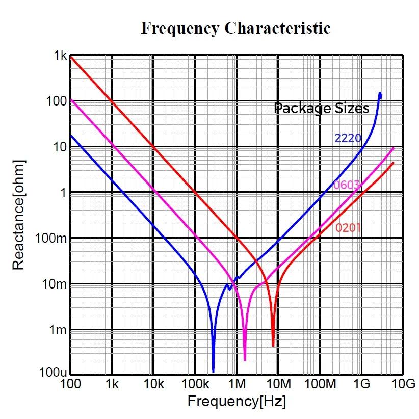
For a real-world capacitor, there are 2 elements worth exploring, ESR(Check older posts to know more about this) and ESL. ESL refers to the inductance that is present in the leads and terminals of a capacitor, as well as any inductance that is present in the capacitor itself. As you see in the equivalent of a capacitor, it’s an RLC circuit, and RLC circuits have a self-resonant freq when the effective inductance and capacitance “cancel” each other and show a minimum impedance. You would have seen those in the V-shaped impedance curves for capacitors. The lowest point of the V shape is the resonant frequency.

After the resonant frequency, Capacitor doesn’t work like a capacitor. An ideal capacitor is supposed to have a lower impedance for larger frequencies of operation. Xc is inversely proportional to Freq. What we see after the resonant freq in the graph, is due to ESL. The inductance of a capacitor starts dominating and the impedance rises. Now, what’s the problem if impedance rises? Suppose you are using a capacitor beyond the resonant freq in your circuit, impedance seen by your power supply rails will be higher, meaning it will actually resist the flow of high freq components creating noise problems or spikes at the switching instant. Hence we always want to use capacitors with lower ESL in our circuits.

The amount of inductance in a capacitor is primarily influenced by the length of its constituent elements. As the length, or loop area, increases, so does the inductance. Consequently, electrolytic capacitors tend to exhibit significantly higher ESL than their 1206 or 0402 (which is even lower than 1206) counterparts. It is therefore advisable to use the smallest possible footprint size that is compatible with the required voltage rating, in order to minimize ESL. You see that on the graphs, the resonant point shits right and the vertical impedance axis value reduces as you go down in size. Another way to reduce it is to use a flipped capacitor(Check older posts on how they work) with a lesser length.

If you liked the post, Share it with your friends!
1 19 20 21 22 23 58