This is a simple resistance measurement technique and fairly widely known, but I rarely see folks whom I usually interact with, using it. The name “Kelvin” comes from Lord Kelvin, who made a bridge circuit to measure smaller resistors.
To measure any resistor, the default method used is to pass a known current through a resistor and measure the voltage across it. Then via Ohms law calculate the resistance value. To understand why 4-wire is needed, you need to understand the issue with a 2-wire measurement. In 2-wire measurements, the resistance of the wires and contacts adds to the resistance of the component under test. This becomes a problem when the component value under measurement is very small. Check images. As the current in both arms are the same, the voltage measured includes the voltage drop across lead resistors also.
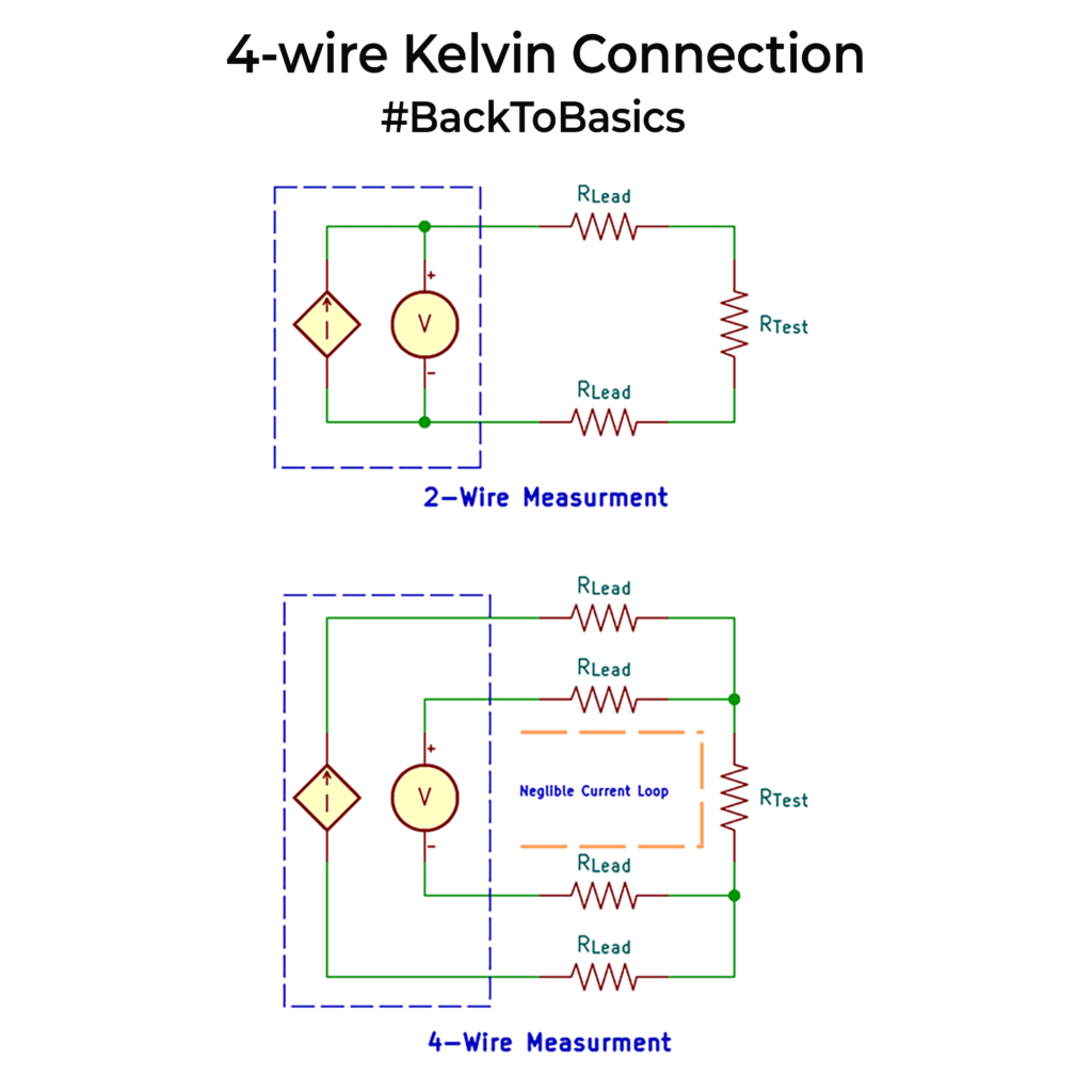
The 4-wire method solves the issue by using one pair of wires to supply the current and another pair to measure the voltage drop across the device. This separation ensures that the voltage measurement is not influenced by the voltage drop in the current-carrying leads, resulting in a much more accurate reading. Since the current flowing to the voltage measurement part is negligible (because of high impedance), measured voltage accurately reflects the resistance of the component alone.
Their application mostly involves measuring milliohm-level resistance values. These can be for measurement of shunt resistors, PCB traces, internal battery resistors. They find their way in precision and calibration instruments.
There are also shunt resistors with 4 terminals that allow you to do this measurement on an actual PCB. Please check my older posts or search the website on how to place and route them in PCBs. Also, if you want to use them, you will get 4 wire Kelvin style connectors with clip on leads. Worth purchasing you if you do a lot of low value resistance measurements.
