Back to Basics: RS232 vs RS422 vs RS485

These are one of the fundamental communication standards out there for sending data between devices. RS stands for “Recommended Standard”. In its simple terms, RS 232 is used for point-to-point communication between 2 devices. You have RX, TX line and you share a GND line between the devices. Its main limitation is the speed of transmission and how immune it is to noise signals. They can do max 1Mbps and can extend the distance to around 15m.
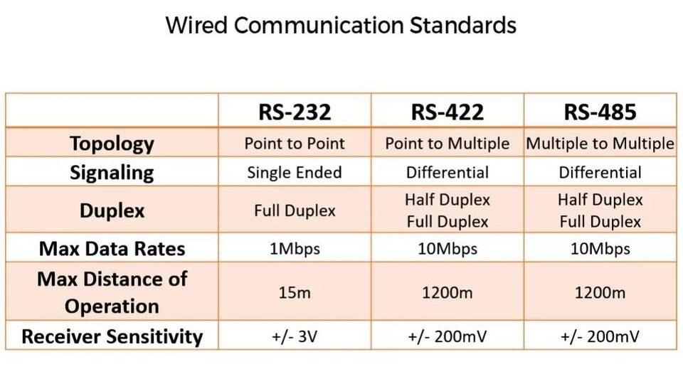
RS422 was introduced to remove the shortcomings of RS232. It supports single-point to multiple-receiver connections. Meaning you can broadcast information. To improve noise immunity, they use a differential pair. So you have just 2 wires running between systems for a half-duplex connection and 4 wires if you want a full duplex. So effectively you have a higher bandwidth (Around 10Mbps) and you can have a longer cabling length of 1000m+. It uses twisted pair lines with a termination of 120 ohms.
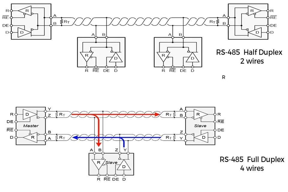
RS485 is again an improvement over RS422 wherein electrical standards remain the same but it introduces the concept of multiple transmitters and receivers in a single line. For RS485, on the driver end, you need to have a minimal differential of 1.5V between lines whereas on the receiver end the differential is 200mV so you do have a large margin for longer transmission of signals. As usual, longer the distance, lower the speed of transmission you can achieve.

It is imperative to understand that, all the above three are electrical standards and not protocols(Protocols define how data is packed and sent) or connector types. It tells you the signal amplitudes, how it can be wired, termination resistance etc but not how to transmit data over it over a signalling scheme. These standards are still in use because it’s cheaper to implement for lower bandwidth wired data transmission between systems.
If you liked the post, Share it with your friends!

Real PCBs have Curves

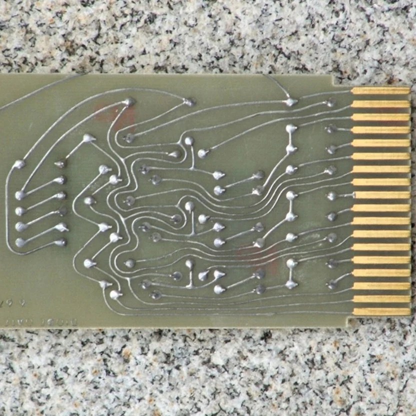
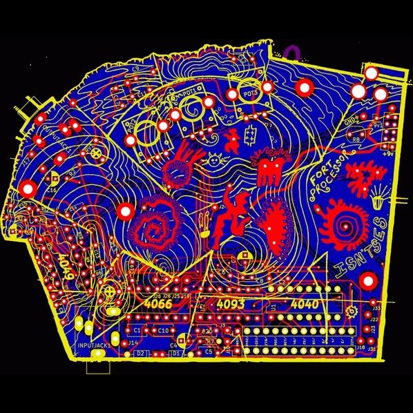
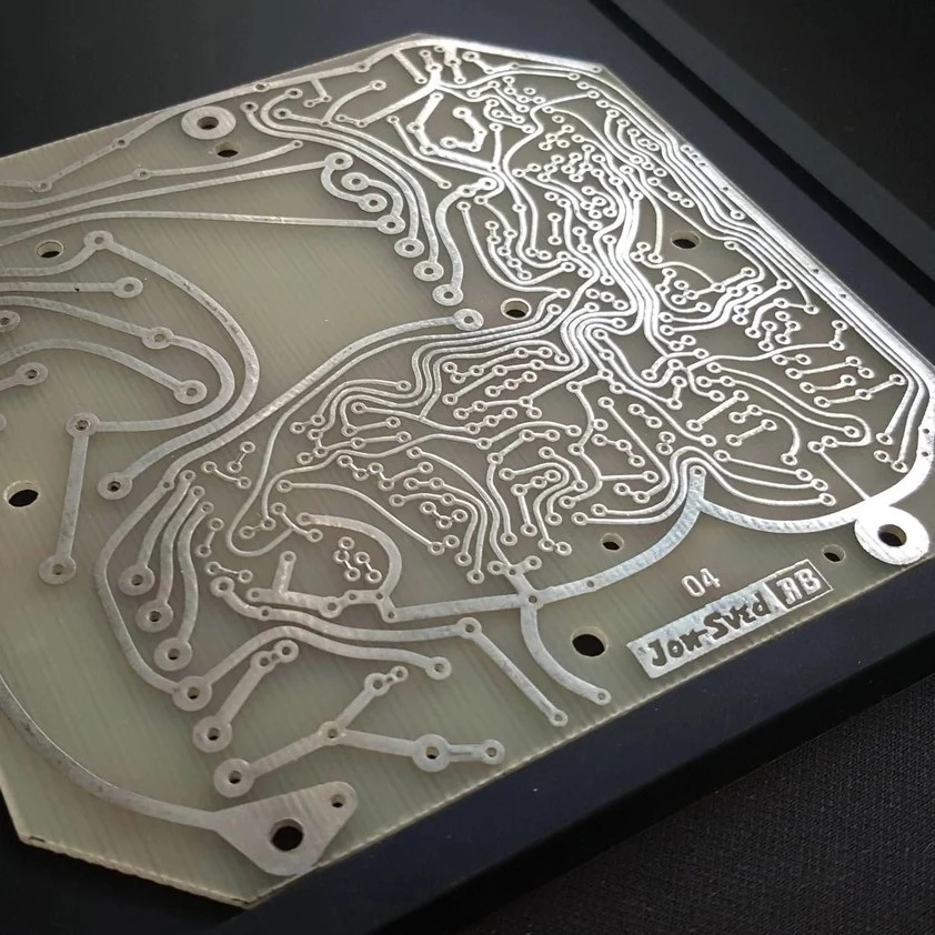
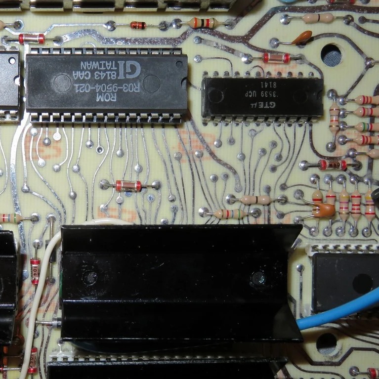
Every once in a while I have been split in my mind about how to route PCBs. There is the current “standard/professional” way of doing it or you can do it using any-angle-routing/curve-routing. To give you a bit more context, the standard routing practice is when you route a PCB on a grid-based board on your favourite CAD tool and you do bends at 45/90 style and all lines are straight and point-to-point. Whereas in curve routing, you bend and turn any different angle and you can smooth it out as if you are doing a free hand drawing. Newer folks in the industry do think that curve routing is absurd.

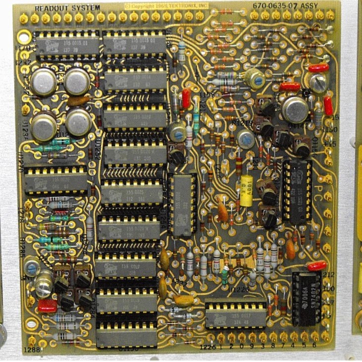
A common issue raised against curve routing is that it looks “ugly”. Even I thought so initially, but when I started questioning, Why does it look ugly? I started to realise its just because it’s different from thousands of boards design which I see out there. My mind is conditioned to think that it’s “ugly” because my “normal” is defined in a certain way. Heck, it doesn’t look organised but it works. There are benefits for curved routing too, like shorter routes between points, lesser impedance discontinuities(in high GHz), and more compact routing as you are not constrained by the grid or angles. Before the age of CAD, folks used to do hand routing of PCBs exactly like this. When CAD became grid based because of the compute-complexity of drawing real-time traces, it shifted to 45/90 routing.

These days although it’s not easily available in all CAD software, some CAD software like Altium(built-in) and Kicad(with a plugin), Topor(with excellent auto-routing capabilities) do provide these options but everyone(including me) keeps using the “standard” way. I do keep wondering if I can ever remove this mental block and adopt it.

Would love to know your thoughts on this. Would you ever use curve routing? Why do you prefer one over the other?

PS: I have compiled a list of pics of curved routing from various sources online to show what people have done.

If you liked the post, Share it with your friends!
1 20 21 22 23 24 58