Been exploring some image sensor tech and Sony’s STARVIS 2 line up looks great. It’s the second-generation “starlight-vision” CMOS tech that runs on many of today’s best low-light security and automotive cameras. They’re impressive because they significantly improve low-light performance, capturing clear images even in near-total darkness. STARVIS 2 delivers higher sensitivity, better dynamic range, and superior near-infrared capture, all without increasing pixel size.
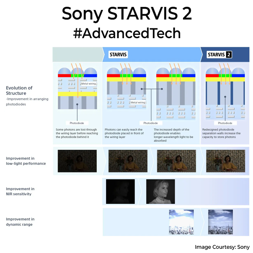
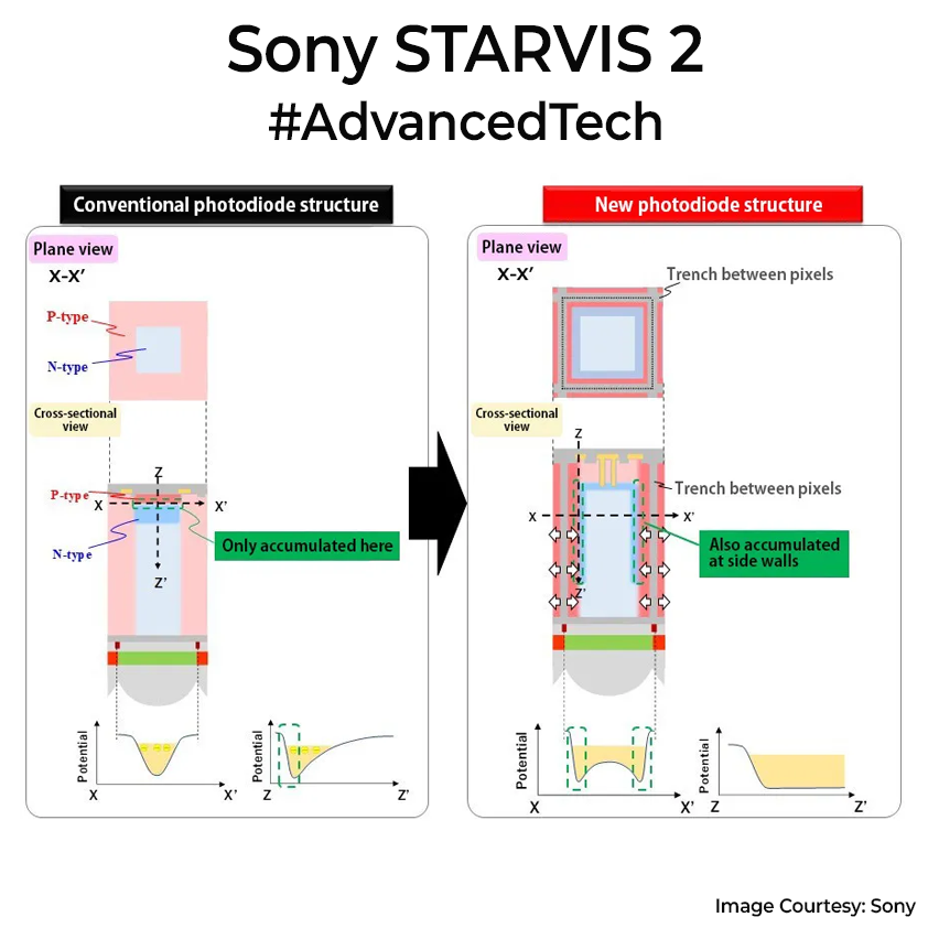
The first STARVIS sensor came out a decade ago, using back-illuminated pixels. This change alone made sensors about 4.6 times more sensitive. Then, in 2021, STARVIS 2 took it further with new tech: deeper vertical photodiodes (not wider, which most companies do) and dual-gain HDR. Deep buckets (vertical photodiodes) extend straight down into the silicon, so they store many more photons without overflowing. IR light penetrates further into silicon before it’s absorbed, so more IR photons are caught. These improvements boost dynamic range by over 8 dB, meaning sensors can clearly capture bright and dark areas simultaneously without blur.
Applications range from security cameras that clearly identify faces at night, traffic cameras capturing license plates in headlights, to dash cams and drones with great low noise performance. So for a normal user purchasing dash cams, make sure you buy once with STARVIS 2 to ensure you can see number plates in bright and low lights. Of course, Sony isn’t alone. They have competitors like OmniVision’s Nyxel, Onsemi’s Hyperlux, and Samsung’s ISOCELL Auto, but Sony is ahead.
Interviews with Sony folks hints at sensors that eliminate the need for shutter exposure times and LED flashes entirely, capturing details from bright sunlight to starlight. This might suggest even deeper wells or some new stacked-pixel designs are on the horizon. Imaging tech will be a nice place to be in when AI robots take off in the next 5yrs.