During some reading, I came across a cooling technology Microsoft published a few months back, and it felt somehwat more interesting than the usual “AI hardware” headline. The work focuses on cooling directly into the silicon itself.
To understand why this is important, we need to understand how chips are cooled today. Most high-power processors rely on cold plates where coolant flows through channels above the package, while heat still has to travel through silicon, thermal interfaces and packaging layers before reaching the liquid. So additional layers adds thermal resistance, and as chip power density keeps increasing, cooling becomes a bottleneck.
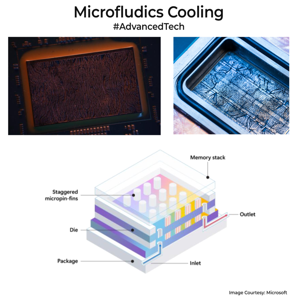
What Microsoft is exploring are microfluidic channels etched directly into the back of the silicon so coolant moves much closer to hotspots on the die. The interesting part for me is the leaf-like channel structure they discussed. Chips do not heat uniformly, so a simple straight-channel layout is inefficient. A branching structure inspired by leaf veins distributes coolant more intelligently toward hotter regions while avoiding unnecessary flow elsewhere. I think they modeled channels with some AI patterning customized to each chip based on the heat produced, mimicking how leaf veins move water/nutrients via branching.
In Microsoft’s lab-scale testing, this reportedly improved heat removal by up to 3x compared to conventional cold plates and reduced maximum GPU silicon temperature rise by as much as 65%, although I would still treat these as controlled research numbers rather than production ones.
Training and inference clusters already consume massive power. Data centres used ~486 TWh in 2025. In inefficient setups, cooling alone can cross 30%, about 146 TWh, enough to power ~12.5 crore Indian homes for a year.
I think the solution in its current format would have reliability issues. Moving coolant this close to silicon introduces risks around clogging, leakage & pressure balance. A tiny blockage inside microscopic channels can impact an entire hotspot region. It might be a while before this rolls out in production.