nRF7002 – The New WiFi chip

nRF7002 Dual Band WiFi6 chip from Nordic Semiconductor

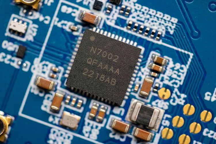
Nordic Semiconductor launched a new WiFi chip last week, nRF7002. They haven’t released the entire information about this chip. It’s in bits and pieces in their press release. Based on what I could gather it’s a low-power, dual-band(2.4GHz and 5GHz) WiFi-6 compatible chip with a physical throughput of 86Mbps in data transfer speeds. On the surface, this looks great for high-throughput WiFi applications. But this seems to work only as a co-processor. Standing alone it can only do Wi-Fi physical layer and MAC layer protocols. It needs an application processor to do the rest of the logic processing. It can be used with Nordic’s usual nRF52, 53 series chips or any other controller out there. This chip interfaces to the application processor via QSPI/SPI. Seems there is a preview development kit(But not available anywhere to buy currently though). If you check the image, there is an nRF7002 on the bottom right which is paired with an nRF5340 chip running the WiFi Stack.
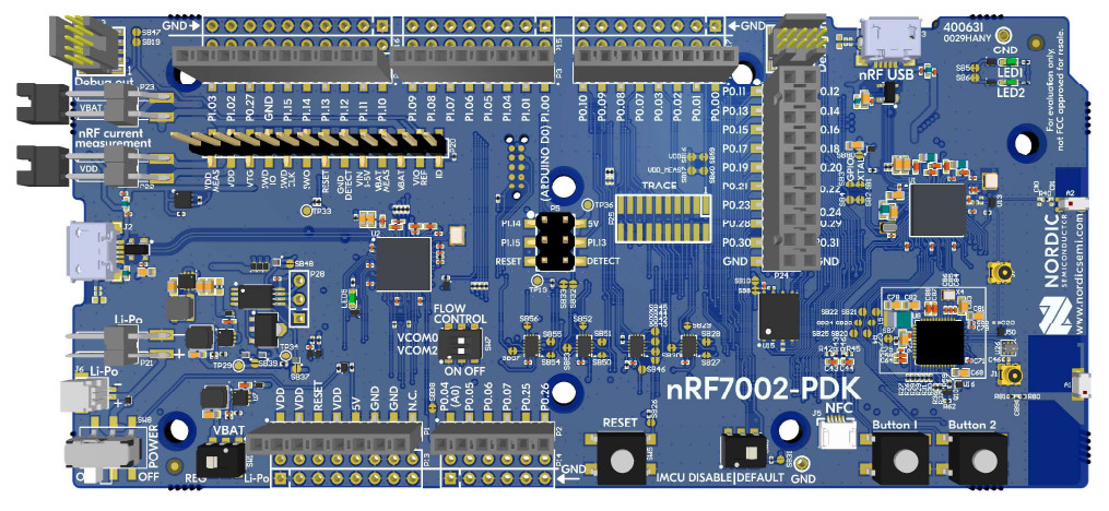
nRF7002 Preview Development Kit with nRF7002(WiFi) + nRF5340(SoC)

Why does all of this matter? Nordic is known for putting out power-efficient and really low-power devices. So there is hope in the community that someone can pull up a relatively low-power WiFi chip. The problem I see with the chip(based on the limited info out there) is that it can’t work as a standalone chip like let a say ESP32 series or a TI WiFi chip. So this chip needs to be really cheap in price so as to make sense. I am sure they are probably working on a dual processor nRF7 series chip which can be totally standalone. Since it’s their first WiFi chip, I do expect issues. But let’s see. The great part is that it can support 5GHz so that won’t use up your 2.4GHz Bluetooth spectrum. SDK also seems to be in very early stages as expected. I am just hoping they improve their documentation because when they launched their first Bluetooth chips, it was pretty bad. It has evolved over the years though. But I have to give them credit for their developer forums, they are exceptionally good and responsive.

Hoping that they are able to pull off a great WiFi chip to compete with ESP32. They are among the very few to have BLE, Cellular and WiFi chips in their lineup. The full Silicon chip launch is slated for the end of the year or early next year.
If you liked the post, Share it with your friends!

Back to Basics: Inrush Current Limiters

Inrush Resistors
Inrush Resistors

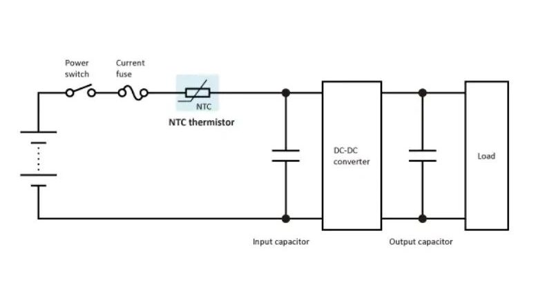
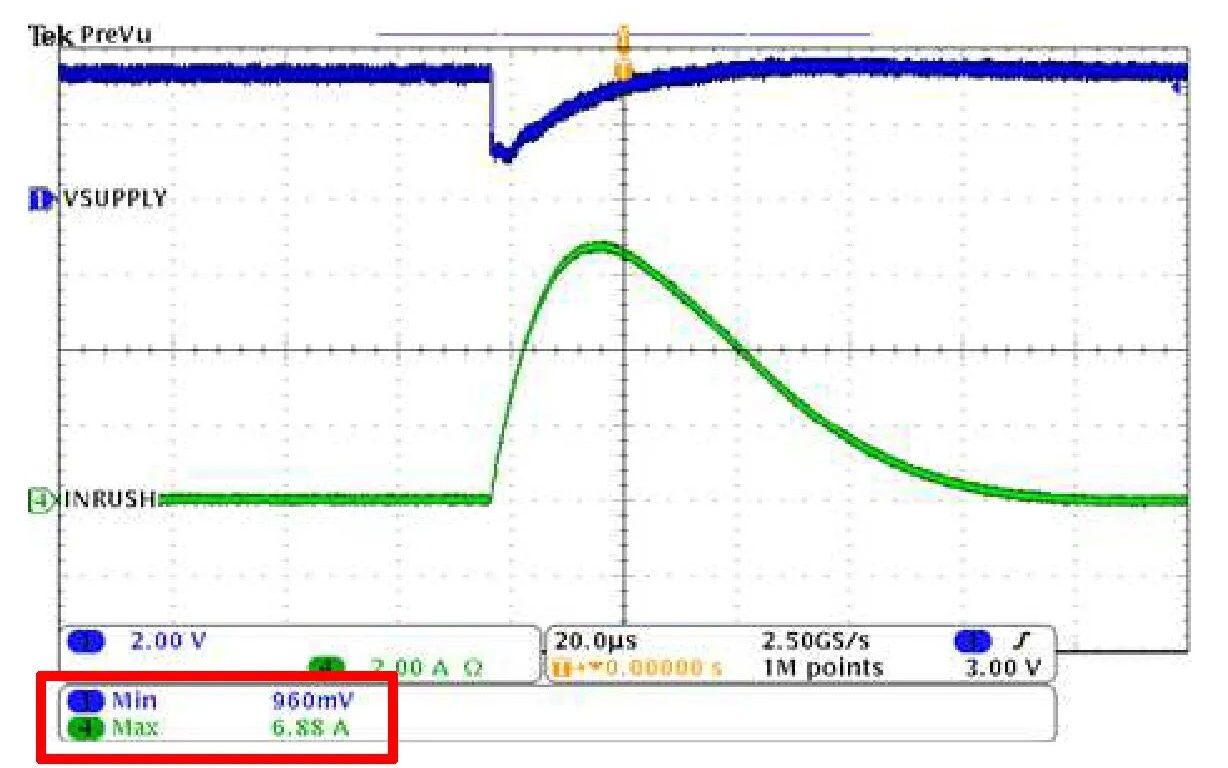
When designing circuits, one of the key elements that are missed by many designers is the addition of inrush current limiters because they are mostly unaware of its use case. Inrush current as the name implies, is a large flow of current at the power on of a device. When PCBs are designed, we do scatter decoupling and bulk capacitors around the entire board to maintain the power supply stability for individual ICs. There can be massive bulk capacitors which are used specifically in large current applications like motors, audio amplifiers etc. When power is off, think of these as massive empty tanks. When the power is turned ON, there will be a massive surge to fill up all these empty tanks and hence you can expect an order of magnitude of instantaneous current flow in the circuit. So why is this large rush a problem? The large draw will immediately collapse your input power rail momentarily by a big factor, now if components of your circuit are not resilient to these power supply changes it can damage parts or may cause temporary glitches at the startup which may not initially be obvious. Even a load capacitance of 100uF can generate a 6.88A of inrush current which can cause a supply rail to drop 3.3V to 960mV. So it’s not something which can be ignored.

You can fix this by adding two things to your circuit, one is an integrated load switch with an adjustable slew rate which limits the rate of current draw for the downstream components. Adjusting the rate drastically reduces the inrush currents. The second method is the one which you see in most circuits is to use NTC thermistors as limiters. Connected in series, these have high resistance when starting off and as soon as current starts flowing, it heats up and the resistance drops to let more current through. So you effectively slow down the inrush requirement. Both have their pros and cons, so next time do check out the need for these in your circuits while building them.

If you liked the post, Share it with your friends!
1 37 38 39 40 41 76