Tech Explained: Taalas AI Inference Chip

A couple of days back I heard about an interesting new startup called Taalas, and they are doing some interesting work in the LLM inference space. I thought we’ll try to deep dive on what I found about that today.

They take a trained model like Llama 3.1 8B and turn it into a fixed chip. Instead of a GPU pulling weights from High Bandwidth Memory(HBM) every token, the weights are baked into silicon in a big ROM like fabric. The model and the hardware are basically the same thing, so you are really buying a specific model in PCIe card form.

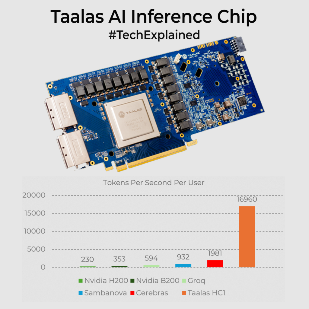
On their first part, HC1, they talk about roughly 17k tokens per second per user for that 8B model at around 200W power. The nearest competitor is the Cerebras chip which does around 2k tokens per sec. With every weight on the die and no HBM in the loop, most of the work becomes local switching instead of moving GBs back and forth. To visualize it, think of a grid where each weight is a tiny logic cell, not a number in memory. When an activation vector arrives, that grid lights up along fixed paths and each cell contributes its small multiply and add. The layer output appears with almost no indexing overhead. SRAM around it holds KV cache and adapters, so you can still add LoRA style tweaks. Try out at chatjimmy.ai It’s mind-blowingly fast, the moment you hit the Enter key.

Where could that be useful? Anywhere you are happy to standardise on a stable model and really care about latency and cost per query. Meaning robots, edge devices, superfast agentic frameworks etc.

Am I really convinced if this is the way ahead? I am not sure. Since it’s baked into the Silicon, you loose flexibility when you want to change things. You need big deployment volumes to make the economics work. By the time a tape out happens(they say 60days), the next generation model would be out there. Also not sure how it scales for large Trillion+ token models. A classic case is for stable popular older models like ChatGPT 4o if its weights are open sourced, its fanboys would love to bake it with Taalas and use for deployment since OpenAI sunsetted the model last week. There is potential lets see where this goes.

If you liked the post, Share it with your friends!

Back to Basics: Auto Balancing Bridge Circuits

I was reading up for a client project on impedance measurements. While digging through, I ran into the auto-balancing bridge circuit used inside many LCR meters, and it’s worth understanding.

In the simplest form, impedance is just Z = V/I. You drive the DUT with a sine, measure the voltage across it, measure the current through it, and then divide. The problem is that an AC ammeter is never ideal. Its input impedance, wiring, and stray capacitance start affecting what you measure.

The auto-balancing bridge avoids measuring current directly. Check the images. Circuit forces the DUT current Ix to flow through a known range resistor Rr using a feedback amplifier. The Low terminal is driven to a virtual ground, close to 0V. Now the current becomes a voltage Vr across Rr, so Vr = Ix * Rr. You also measure Vx across the DUT. Put those together and you get Zx = Vx / Ix = Rr * (Vx / Vr). The instrument is really doing a vector ratio(Vx / Vr).

This setup would use two vector voltmeters, one for Vx and one for Vr, then take the ratio. The catch is there can be mismatch between meters. So many LCR meters instead switch one voltmeter receiver between Vx and Vr, so the same front end measures both and tracking error largely cancels.

Below about 100 kHz, an op-amp transimpedance stage can hold the Low node near 0V and convert Ix into Vr. Above that, bandwidth limits and parasitics make the balance drift. So instruments add a null detector that senses leftover error current, split it into 0° and 90° parts, and drive a vector modulator to tweak amplitude and phase until the error goes to zero. That closed-loop correction is the auto in auto-balancing. BTW, its called auto-balancing because the instrument doesn’t rely on you to manually “balance a bridge” like old Wheatstone-style bridges. It uses a feedback loop that continuously drives the error toward zero on its own.

You use this circuit for getting your impedance U curves for capacitors, ferrite beads etc to a particular freq limit. For very high freqs (GHz), you often switch to network analysis/VNA methods.

If you liked the post, Share it with your friends!
1 4 5 6 7 8 134