Newer folks usually pick a MOSFET by chasing the lowest RDS(on) on the valid assumption that lower resistance means lower I²R loss. So it feels like a good way to keep the device cool. But that does not always give you the lowest-running design once the MOSFET is switching. Let’s discuss that today.
RDS(on) mainly tells you about conduction loss when the device is fully on. That matters a lot in high-current paths. If the current is high and switching speed is small, low RDS(on) will help. But in a converter, heat is not only coming from on-state loss. It also comes from the time the MOSFET spends moving between off and on.
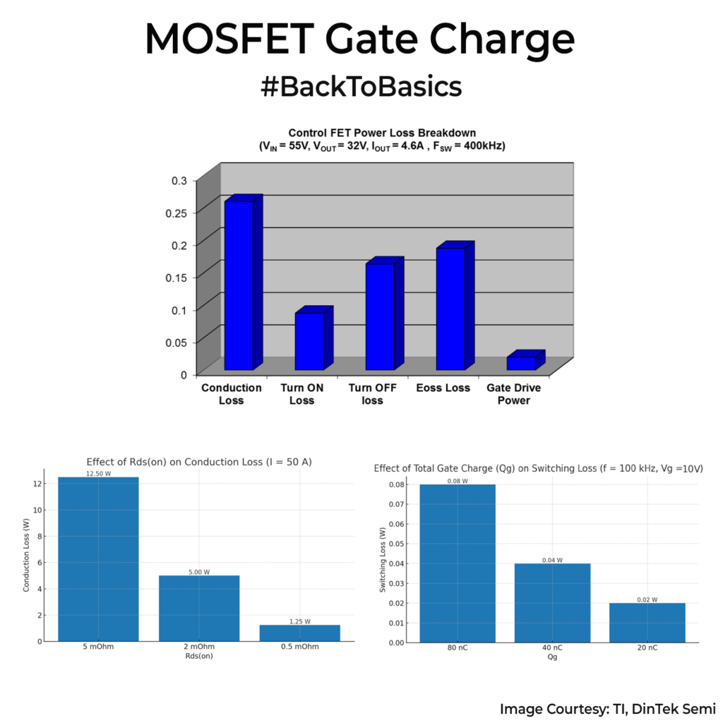
This is where gate charge(Qg) comes in. Gate charge is the charge the driver must push into the gate every cycle. More charge often means slower transitions for the same driver current. Slower transitions mean more overlap of voltage and current during switching, and that means more switching loss. You also burn power in the gate driver, because charging and discharging the gate every cycle takes energy.
This is why a MOSFET with low RDS(on) can still run hotter than expected. To get that low resistance, the device silicon usually needs to use a larger die area. That typically brings higher capacitance and higher total gate charge. So you save conduction loss, but give some of it back in switching loss, especially at higher frequency.
So how do you choose then? Low RDS(on) helps when conduction loss dominates. Low gate charge helps when switching loss dominates. You can’t choose one in isolation. You try to find a balance that matches your current, voltage, switching frequency, and gate driver strength.
My rule of thumb is at lower frequency and higher current, care more about RDS(on). At higher frequency, look into Qg. A part with slightly higher RDS(on) but much lower Qg can run cooler in the real circuit.
Remember that two MOSFETs with similar input capacitance can switch very differently, so the gate charge curve often tells you more than just one capacitance number.